Lithium-ion Battery Recycling Machine- Xingmao MachineryLithium-ion Battery Recycling Plant- Xingmao Machinery

Rotary Pyrolysis Kiln
Carbonisation Furnace

Rotary Pyrolysis Kiln

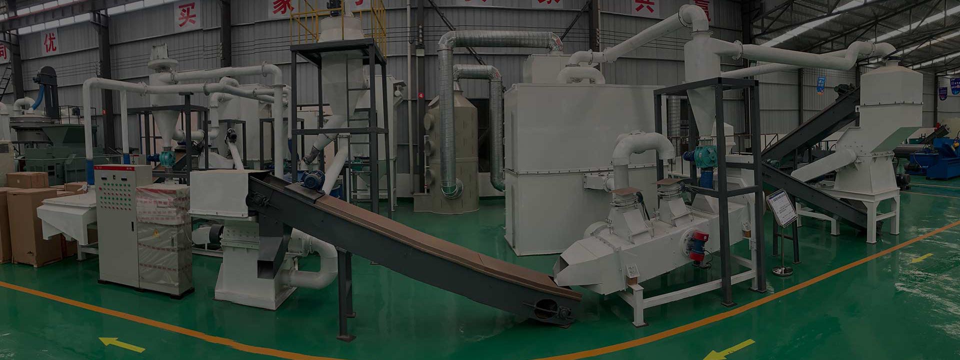
Capacity:500-10000kg/hRaw Materials: Biomass, plastics, rubber, e-waste, used lithium batteries ect.

Final Products: Solid residue.

Home > Products > Carbonisation Furnace
Product Details

Rotary pyrolysis carbonisation kilns and systems for: biomass, plastics, rubber, electronic waste, used lithium batteries, catalysts, sludge and other materials that can be pyrolysed to carbon compounds. For solid waste recycling treatment pyrolysis is the commonly used method. It is also the most common way of waste solid waste treatment at home and abroad. The pyrolysis method is used to treat solid waste, recycling, reuse as heat into energy. Thermal treatment is usually divided into: incineration and pyrolysis. Incineration is the solid waste through high temperature decomposition and deep oxidation comprehensive treatment process. A large number of solid waste fast powder slightly ash slag and tail gas. But its investment cost is large, the operating cost is very high. In the process of incineration is prone to dioxin and other harmful substances. It needs to be eliminated by secondary combustion at a high temperature of 1200 degrees. Pyrolysis: Through carbonisation, organic and inorganic materials are heated to produce sufficient cracking. They are cracked according to their hydrocarbon ratio. Gas phase (pyrolysis gas) and solid phase (solid residue) with high utilisation value are formed.

Rotary Pyrolysis KilnProduct Details
Solution
The rotary pyrolysis kiln system comprises a cylinder with a heating chamber on the outside, an inlet at the front part of the cylinder, an outlet at the rear end and a pyrolysis gas outlet. A flue gas outlet is provided above the heating chamber. The inlet port is connected to a feeding system and the outlet port is connected to a solid slag cooling system. The pyrolysis gas outlet is connected to a pyrolysis condensation system. The heat source combustion chamber and burner are connected to the flue gas inlet. The flue gas outlet is connected to a waste heat recovery system. The waste heat recovery system is connected to the burner inlet. The pyrolysis gas condensation system is connected to the end of the gas purification and collection device and recycling device. The recycling exercise is connected to the hot air furnace. The recycling system includes a water sealing device, a natural gas fan, a gas water sealing device at the end of the pyrolysis gas condensation system, and a combustion fan into the burner. The feed system includes a silo, and a feed screw reamer. The silo is connected to the feed screw reamer via a feed airlock box. The tail end of the feed screw reamer is connected to the feed opening of the rotary kiln. The front end of the burner is provided with a fuel inlet, a combustion air as soon as possible and a pyrolysis gas inlet. The waste heat recovery system includes a waste heat recovery device, which has two inlets: one is connected to the combustion fan, and the other is connected to the flue gas. Waste heat recovery device has two outlets, one outlet for the combustion air inlet of the combustion chamber is connected, the other outlet is linked to the induced draft fan, gas purification and treatment devices and chimneys and so on.


The discharge cooling system includes a discharge cooler, provided with a discharge airlock, and the discharge airlock is connected to the discharge cooler.
The pyrolysis gas condensation system includes: a gas and solid separator, a spray tower, and a condenser. The gas and solid separator is connected to the pyrolysis gas outlet. There is a circulating water pump inside the spray tower, and the spray tower and condenser bottom army yo connect to the liquid collection system.

 
Rotary Pyrolysis KilnProcess Flow
Process Flow

1. The material to be treated passes through the silo and is fed into the feed screw reamer and then into the pyrolysis rotary kiln through the feed airlock, which can be a rotary discharge valve.
2. The high temperature flue gas from the burner is fed into the pyrolysis rotary kiln through the gas pipeline for heating. The material in the kiln is heated indirectly. 3.
3. The materials are heated in the kiln. The material is heated by the colleague, and then after turning, pouring, and gradually towards the discharge port, using the spiral conveying device. After completing the pyrolysis, the material is excluded.
4. materials in the rotary kiln and outside the high temperature flue gas can be indirectly heated, materials in the heat pyrolysis of hydrocarbons, inorganic substances, such as high temperature pyrolysis of substances occurring pyrolysis. Produce pyrolysis gas. Solid slag after pyrolysis. 5.
5. through the pyrolysis gas outlet into the gas and solid separator to remove dust, and then through the pyrolysis gas condensing device. The condensable components are condensed and collected. The non-condensable gas is then incinerated in a high temperature furnace before entering the gas cleaning system. The solid slag is collected after being cooled by a cooling reamer. Generally, cooling water is mainly used as the medium sword-cooled structure.
 

Technical parameters
The rotary kiln has high thermal efficiency, large processing capacity, tight sealing, uniform heating, easy to control the temperature, pyrolysis time and so on. Relatively more environmentally friendly and efficient than solid waste incineration. Applicable to: waste plastics, electronic waste, biomass, waste rubber, waste lithium batteries and other industry sectors. The whole set of production line adopts advanced technology, environmental protection and high efficiency, with high economic benefits and social value. Equipped with waste heat recovery system, the flue gas after heat exchange through the pyrolysis rotary kiln passes through the pyrolysis rotary kiln. The flue gas enters the waste heat recycler. The heat exchange can be used to preheat the combustion air. After the waste heat recovery, the flue gas passes through the induced draft fan into the flue gas purification and treatment device. The flue gas is discharged after it has been treated to the required standard. The heat can be reused from the points, and the pyrolysis efficiency is high. It can realise the gradual use of energy and energy saving and emission reduction. In addition, pyrolysis gas condensation system recycling system. Pyrolysis gas passes through the spray tower for rapid cooling. Condensable substances are condensed in the intercooler. The condensable substances are in liquid state. A portion of the non-condensable gas passes through a fan for incineration in a hot air furnace. Thus the recovery of non-condensable gases is realised.
Online Message
Hot Products
Hot News

Home

Products

Inquiry

Tel